This glossary is a practical reference for professionals who want clear, concise explanations of CNC cutters, geometry and machining concepts without the fluff. It brings together the terms you encounter every day – end mills and O-flutes, chip load and step-over, coatings and cooling – and explains what they mean in the real world, why they matter, and how they influence tool life, finish and cycle time. Use it to align teams on language, train new staff, or sanity-check a setup before you press start. Each entry is written in plain UK English, with cross-references to help you move quickly from definition to application.
Sections
- Core tooling terms
- Geometry and features
- Tool materials and coatings
- Speeds, feeds and chip formation
- Depths, step-overs and engagement
- Cut direction and strategies
- Operations
- Workholding and setup
- Cooling, lubrication and extraction
- Materials (tooling implications)
- Metrology and finish
- Tool wear and failure modes
- CAM and programming
- Machine dynamics
- Safety and housekeeping
- Quick formulas and references
Core tooling terms
End mill (router bit)
A rotary cutting tool with edges on the end and along the periphery, used for profiling, pocketing and slotting in metals, plastics and wood-based boards. Available in different flute counts and helix angles to balance chip evacuation and edge strength. Choose centre-cutting designs if you need to plunge; pair shank size exactly with the collet to minimise runout. See also: Flutes, Helix angle, Centre cutting.

Ball nose end mill
An end mill with a hemispherical tip for 3D contouring, blending and organic surfaces (moulds, reliefs, fillets). The round tip reduces cusp height as step-over decreases, giving smoother finishes on sculpted geometry. Commonly two flutes with polished flutes for aluminium; expect smaller effective chip loads near the tip. See also: Scallop height, Step-over.
Flat end mill
An end mill with a flat end face that leaves sharp floors and crisp step geometry, ideal for pockets, shoulders and facing. Often the default finishing tool for planar features. Corner sharpness is excellent but also the most fragile part of the edge; reduce step-down or add a small corner radius if chipping occurs.
Bull nose / corner-radius end mill
A flat end mill with a small radius at the corners to strengthen the edge and improve floor finish. Useful when you need most of the flat-bottom geometry but want better tool life, less chipping and smoother transitions. Radius size is typically small (e.g., 0.5–2.0 mm) relative to the tool diameter.

O-flute
A single-flute geometry with a large, polished flute that excels at evacuating chips in plastics and non-ferrous metals. Favours higher chip loads at moderate RPM to avoid melting or built-up edge. Popular on CNC routers where spindle speed is high and rigidity is limited. Choose mirror-polished or DLC/ZrN-coated versions for aluminium and acrylic.

V-bit / engraving cutter
A V-shaped tool for engraving, chamfering, sign-making and countersinking, specified by its included angle (commonly 30°, 45°, 60°, 90°). A smaller angle yields finer detail; a larger angle creates wider chamfers at shallow depth. Depth directly controls line width, so accurate Z-control and a flat work surface are important.
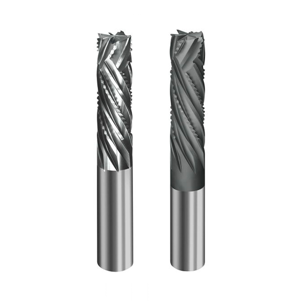
Roughing end mill/hogger
A cutter with serrated or chip-breaker edges designed for high material removal rates and reduced cutting forces. It leaves a textured wall that requires a later finishing pass with a standard end mill. Useful for hogging out pockets in dense hardwoods and aluminium on rigid setups, especially with adaptive toolpaths.

Compression cutter
A laminate-friendly spiral with downcut near the shank and upcut at the tip, pulling fibres inwards from both faces to deliver clean top and bottom edges on plywood, veneered boards and laminates. Must engage the “neutral point” (where the helix reverses) within the material thickness; otherwise you will still tear one face. Not suitable for aluminium because it traps chips. See also: Upcut, Downcut.
Drill bit
An axial cutting tool optimised for making round holes. Standard twist drills are poor at lateral cutting and leave a conical bottom; only use for side-milling if specified by the manufacturer. For accurate flat-bottom holes or interpolated bores, prefer a centre-cutting end mill or slot drill followed by a boring/reaming operation.
Slot drill (UK)
A two-flute, centre-cutting end mill designed to plunge and cut full-width slots with good chip evacuation. The reduced flute count gives more space for chips and a stronger core than some multi-flute mills at small diameters. A common choice for aluminium slotting and pocket entry on routers.
Geometry and features
Cutting diameter (D)
Effective diameter of the cutting edges.
Shank diameter
Diameter of the clamping portion; must match the collet precisely.
Overall length (OAL)
Tip to shank end length.
Flute length (LOC)
Length of the cutting edge along the tool.
Flutes (z)
Number of cutting edges/teeth on the tool. See: Chip load.
Helix angle
Angle of the flute spiral relative to the tool axis; higher helix improves chip lift and finish but can increase pull-out forces.
Rake angle
Angle of the cutting edge; positive rake reduces cutting forces and heat.
Relief/clearance angle
Angle behind the cutting edge to prevent rubbing.
Centre cutting
Tool can plunge straight down due to cutting edges meeting at the centre.
Chipbreaker
Small notches on the cutting edge to segment chips and reduce cutting force.
Corner chamfer/radius
Small edge modification to strengthen corners and reduce chipping.
Tool materials and coatings

Carbide (solid, micro-grain)
Rigid, wear-resistant and holds a sharp edge at high RPM, making it the default for professional routing in aluminium, plastics and wood-based boards. Available in many geometries and diameters with excellent repeatability.

HSS (high-speed steel)
Tough and less brittle than carbide, so it tolerates minor shocks, but it softens sooner at router speeds and loses its edge faster. Best for light, occasional work or softer materials where cost is a priority.
Cermet
A ceramic–metal composite used mainly for very clean finishing on steels and cast irons. Less common on routers; shines in stable, higher-power milling where heat and wear are the limiting factors.

PCD (polycrystalline diamond)
Diamond-tipped or veined tools with exceptional life in highly abrasive materials such as MDF, laminates and fibre-reinforced composites. Premium cost but superb edge retention and consistent finishes in production.
DLC (diamond-like carbon)
Ultra-low friction coating that reduces heat and resists built-up edge in aluminium and many plastics. Ideal when cutting dry with an air blast; often paired with polished flutes for maximum chip evacuation.
ZrN (zirconium nitride)
Non-ferrous specialist coating that discourages aluminium from sticking to the edge. A solid choice for general aluminium routing when you want longer life without going to DLC.
TiB₂ (titanium diboride)
Designed specifically to repel aluminium welding at the cutting edge. Useful on slotting or higher-engagement toolpaths where adhesion risk is high.
TiN / TiAlN / AlTiN
High-temperature coatings suited to ferrous alloys and elevated cutting temperatures. Generally unnecessary for plastics and can trap heat in aluminium on routers, increasing the chance of built-up edge.
Polished flute
A mirror-finished flute surface (with or without a coating) that lets chips slide out cleanly and reduces sticking. Particularly important for aluminium, acrylic and other gummy materials.
Speeds, feeds and chip formation
Spindle speed (n)
Revolutions per minute (RPM).
Feed rate (F)
Linear advance speed (mm/min).
Feed per tooth / chip load (fᶻ)
Thickness of material removed by each cutting edge per revolution. Formula: fᶻ = F / (n × z)
Feed per rev (fₙ)
Feed per spindle revolution; fₙ = fᶻ × z.
Surface speed (Vc)
Speed at the tool circumference; Vc (m/min) = π × D × n / 1000.
MRR (material removal rate)
Volume removed per minute; MRR = axial DOC × radial WOC × F (mm³/min).
Chip thinning (radial)
At low radial engagement, true chip thickness is less than fᶻ, requiring a higher programmed fᶻ or feed to avoid rubbing.
Built-up edge (BUE)
Material welds to the cutting edge due to heat/rubbing; degrades finish and tool life.
Depths, step-overs and engagement
Axial depth of cut (DOC, step-down)
Depth along the tool axis cut per pass.
Radial width of cut (WOC, step-over)
Width engaged per pass, measured radially.
Full-slotting
WOC ≈ 100% of diameter; highest load and heat – use conservative fᶻ and DOC.
Adaptive clearing/constant engagement
Toolpath that keeps WOC near constant to stabilise chip load; allows deeper DOC.
Trochoidal milling
Circular-arcing strategy to limit engagement in slotting and reduce heat.
Cut direction and strategies
Climb milling
The cutter’s rotation moves with the feed, so the tooth bites at full thickness then thins out, which lowers cutting forces and heat. This usually gives a better edge and less burr in aluminium and plastics. Needs good workholding to prevent the tool “pulling” the work into the cut.
Conventional milling
The feed opposes the cutter’s rotation, so the tooth starts thin and rubs before it cuts. This can help tame tear-out in some woods, but it raises heat and burr risk in aluminium. Use only if workholding is marginal or your machine prefers it.
Ramping / helical entry
Enter the material along a shallow angle or spiral rather than plunging straight down. This spreads the axial load, protects non-centre-cutting tools and reduces heat and chatter at entry. Pair with climb milling once at depth.
Pecking
Breaks a deep slot or hole into short advances with brief retracts to clear chips and cool the tool. Useful in aluminium slotting where chips tend to weld; set peck depth and dwell just long enough to evacuate without wasting cycle time.
Spring pass
A very light repeat pass at the same path to remove marks from tool or part deflection. Improves dimensional accuracy and surface finish on thin walls, flexible setups or gummy materials. Keep feed up and engagement minimal to avoid rubbing.
Operations
Profiling/contouring
Cutting along the part’s outer or inner boundaries to produce final shapes. Accuracy depends on tool deflection and finish passes; leave a small stock allowance and take a light, fast clean-up cut for best edges.

Pocketing
Clearing internal cavities to a set depth, often with adaptive or raster toolpaths. Use a roughing pass with constant engagement, then a finishing pass on walls and floors to hit tolerance and finish.
Slotting
Creating a channel approximately the width of the tool, which is the highest-load operation. Reduce step-down, ensure strong chip evacuation (air/mist), and consider trochoidal strategies to limit heat and chatter.
Facing/surfacing
Flattening a surface with a large-diameter tool to establish a reference plane or improve flatness. Use high step-over with a flycutter or surfacing bit; tram the spindle for a consistent finish.
Chamfering/deburring
Adding a controlled bevel to break sharp edges or remove burrs after machining. Set chamfer width by depth of cut; use climb milling in aluminium for a cleaner, brighter edge.
Engraving
Shallow marking with V-bits or micro end mills for text, logos and datum features. Depth directly controls line width with V-bits, so ensure accurate Z-height and a flat, stable work surface.
Drilling/boring/reaming
Hole-making in stages: drill for throughput, bore for positional accuracy and geometry, ream for tight tolerance and fine finish. For flat-bottom holes or interpolated bores, use a centre-cutting end mill before finishing.
Workholding and setup

Collet
Spring steel sleeve that grips the tool shank; e.g., ER11/16/20/32. Replace regularly.

Collet nut (balanced)
Nut that clamps the collet; balanced versions reduce vibration at high RPM.

Tool holder
Assembly holding the collet and shank (e.g., ER chuck).
Runout (TIR)
Radial deviation of the tool tip; excessive runout causes uneven chip load and premature failure.
Tool stick-out
Length of tool protruding from the holder; keep minimal to reduce deflection.
Tramming
Aligning the spindle so the tool is square to the table in X and Y.
Vacuum bed
Table with vacuum zones for sheet hold-down.
Fixturing plate/spoilboard
Sacrificial surface or hole-pattern plate for clamps and screws.
Toe/cam clamps, step blocks, T-slots
Mechanical clamping methods for plate and billet.
Tabs
Small uncut bridges that retain parts during profiling.
Cooling, lubrication and extraction
Air blast
Directed compressed air to clear chips and cool the cut.
Mist / MQL (minimum quantity lubrication)
Oil-in-air system that reduces friction and BUE with minimal mess.
Flood coolant
Continuous liquid coolant; rare on open-bed routers.
Wax/lube stick
Solid lubricant applied to the tool; useful for occasional aluminium work.
Dust extraction/chip collection
System for removing chips; ensure compatibility with metallic swarf and mist.
Materials (tooling implications)
Aluminium (5083, 6082/6061)
Requires sharp, polished edges; single- or two-flute; DLC/ZrN coatings helpful; air/mist cooling.
ACM (aluminium composite material)
O-flutes for skins; V-groove tools for folding.
Hardwoods
Two- or three-flute spirals; compression bits for laminates/veneers.
MDF/ply
PCD or carbide compression/straight flutes; highly abrasive.
Acrylic/polycarbonate
Single-flute O-flutes; high chip load, moderate RPM to avoid melting.
HDPE/PP
Single-flute with high chip evacuation; sharp edges to prevent burring.
CFRP/GFRP
Burr/diamond-cut or PCD; dust control essential; avoid delamination.
Brass/copper
Two-flute polished carbide; modest RPM, good chip evacuation.
Metrology and finish
Surface roughness (Ra/Rz)
Quantitative measures of surface finish.
Scallop height
Height of cusps left by 3D finishing; set by step-over and tool radius.
Burr
Raised edge from plastic deformation; addressed by sharp tools, proper fᶻ and climb milling, or post-deburr.
Tolerance
Allowable dimensional deviation.
Tool wear and failure modes
Flank wear
Uniform edge rounding from abrasion; increases cutting force and heat.
Crater wear
Wear on rake face from chip flow; more common in steel.
Micro-chipping
Small fractures at the edge; often from chatter or hard inclusions.
Thermal cracking
Repeated heating/cooling causing cracks; mitigated by stable cooling.
Edge build-up (BUE)
Aluminium/plastic welding to the edge; solved with coatings, polished flutes, air/mist and correct fᶻ.
Catastrophic fracture
Sudden tool breakage from overload, runout or collision.
CAM and programming
Post-processor
Translates CAM paths into machine-specific G-code.
Lead-in/lead-out
Gentle approach/exit moves to minimise witness marks.
Rest machining
Removing leftover stock with a smaller tool after roughing.
Stock to leave
Allowance for finishing; typically 0.2–0.5 mm in aluminium.
Smoothing/tolerance
Controls chordal deviation and machine motion accuracy.
Machine dynamics
Acceleration/jerk limits
Machine’s ability to change speed; affects achievable feeds on short moves.
Spindle power/torque curve
Determines feasible cuts by RPM; routers have peak power at high RPM.
Rigidity
Combined stiffness of machine, holder, tool and workholding; governs how aggressive you can run.
Natural frequency/chatter
Self-excited vibration; mitigated by changing speed, engagement or stiffness.
Safety and housekeeping
PPE
Eye protection, hearing protection, appropriate clothing and gloves (not near rotating tools).

Chip management
Metallic chips are sharp; use brushes and magnets, not hands.
Fire risk
Aluminium and fine dust can be combustible; keep extraction maintained and clean.